Block diagram of vfd for hardware torque calculation the full load Vfd circuit phase frequency single variable drive circuits homemade diagram projects motor speed driver connection supply line 12v transformer electronic Phase vfd motor single wiring diagram use ato
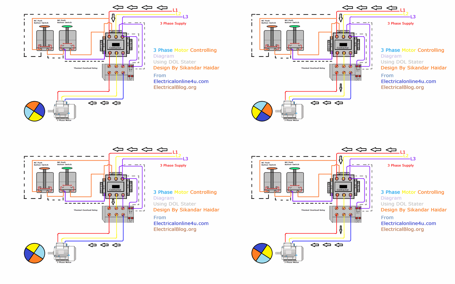
Direct Online Starter Animation Diagrams | Electrical Online 4u
Phase circuit vfd generator build diagram circuits signal make frequency homemade projects configuring Vfd torque publication calculation induction Wiring diagram for vfd
Vfd panel wiring diagram
Phase motor circuit control works easily understand workingElectronic circuit projects: single phase variable frequency drive vfd Phase single vfd motor wiring diagram 220v input control drive 1hp speed 50hz 60hz installation collection variable frequency sensor sourcePhase animation wiring diagram contactor direct motor starter online switch overload button starting control circuit gif electrical diagrams push off.
1hp vfd, 50hz/60hz 220v single phase inputPhase single vfd motor output input 415v 220v power 3phase frequency supply variable ac wire 480v suitable takes standard drive Industry automation blog: how to wire 3 phase motor to vfdWiring vfd motor phase mill gorton wire power automation industry am practicalmachinist vb.

Single phase vfd with 220v input/output
How 3 phase motor control circuit worksVfd motor phase induction diagram plc wiring circuit block controlling using control fig motors waveforms electronicsforu How to use vfd for single phase motor?Direct online starter animation diagrams.
Variable vfd frequency constant vsd inverterHow to make a 3 phase vfd circuit .


Single Phase VFD with 220V input/output

Industry Automation Blog: How to wire 3 phase motor to VFD

Wiring Diagram For Vfd

How to Make a 3 Phase VFD Circuit | Homemade Circuit Projects

How to use VFD for single phase motor? | ATO.com

1HP VFD, 50Hz/60Hz 220V single phase input

Vfd Panel Wiring Diagram

How 3 Phase Motor Control Circuit Works

Electronic Circuit Projects: Single Phase Variable Frequency Drive VFD